PN532 boards often support I2C, SPI or UART; jumpers must match the workflow.
NFC and RFID module
PN532 ESP32 wiring, pinout and NFC I2C setup
Wire a PN532 NFC/RFID module to ESP32 or ESP32-S3, check the pinout, set the interface jumpers and start with I2C tag reads before write-capable lab tag tests.
Use this page for PN532 ESP32 wiring, especially I2C modules with selectable HSU/I2C/SPI jumpers. Confirm mode, pull-ups and voltage before read-only tag tests.
- PN532 pinout
- NFC
- I2C setup
- RFID
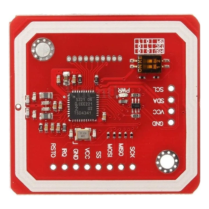
pinout photos
PN532 pinout photos and jumper mode reference
Compare your PN532 board with these reference photos before wiring. PN532 V3, Adafruit and clone modules can expose different headers or switch labels; follow the shown pin order only when your silk-screen matches VCC/GND/SDA/SCL, SCK/MISO/MOSI/SS, IRQ/RSTO and the HSU/I2C/SPI mode table.
ESP32 I2C setup
PN532 ESP32 wiring and mode selection
Many PN532 boards fail because they are still set to HSU or SPI mode. Match the visible jumper table on your board before trying an I2C scan.
| PN532 connection | ESP32 Bit Pirate connection | Setup check |
|---|---|---|
| VCC | 3.3 V module supply | Confirm the breakout accepts the voltage you are using. |
| GND | Common ground | Share ground before scanning for the reader. |
| SDA / SCL | Selected I2C pins | Check pull-ups, pin order and the configured I2C pins. |
| Interface switches | I2C mode for the recipe path | Set HSU/I2C/SPI jumpers exactly as the board label shows. |
| IRQ / RSTO | Optional GPIO | Only wire these when the workflow or firmware mapping requires them. |
| SPI / UART headers | Alternative modes | Use SPI or UART only when the workflow explicitly supports that mode. |
workflow
Start with read-only PN532 tag tests
Confirm the PN532 interface jumpers, I2C address, voltage and pull-ups before scanning. Start with a read-only tag identify, then keep write or clone tests limited to compatible lab tags.
- 01
Set the PN532 module to the supported interface mode, usually I2C for these workflows.
- 02
Wire power, ground, SDA and SCL with the correct pull-ups and voltage.
- 03
Start with tag read/identify before write or erase workflows.
- 04
Use write/erase/clone flows only on lab tags designed for that purpose.
- 05
Keep NFC/RFID tests limited to tags you own or are authorized to test.
Example CLI flow
mode rfid
read
clone
write
erase
Use this PN532 sequence for interface detection and read-only tag identification before write-capable tag tests.
hardware reminders
PN532 NFC wiring notes before tag scans
Confirm PN532 interface jumpers, I2C address or SPI select, pull-ups and module voltage before tag scans.
Wiring View
Not every tag supports every operation.
Do not test access cards or tags without permission.
Before wiring a module or target chip, check pinout, voltage, ground reference and whether the selected ESP32-S3 board has the required pins free.
task-level guides
Detailed PN532 NFC/RFID module recipes
Use these PN532 guides for interface selection, tag identification, read-only checks and compatible lab tag writes.
Wire PN532 RFID reader in I2C
Task-level guide with wiring, commands and troubleshooting steps.
Read RFID tag with PN532Task-level guide with wiring, commands and troubleshooting steps.
Erase RFID test tag PN532Task-level guide with wiring, commands and troubleshooting steps.
Clone MIFARE UID magic cardTask-level guide with wiring, commands and troubleshooting steps.
what it is
What PN532 is used for
PN532 modules are NFC/RFID reader boards often used for tag identification and controlled lab tests with compatible tags.
practical value
Why use PN532 with ESP32 Bit Pirate
ESP32 Bit Pirate connects PN532 wiring and tag workflows to the same I2C, recipe and serial tooling used across the project.
common symptoms
Common problems with PN532 NFC/RFID module
PN532 failures usually come from interface jumpers, I2C address, pull-ups, voltage or unsupported tag operations.
No I2C address
Check interface jumpers, pull-ups, SDA/SCL order and power.
Tag not detected
Check antenna orientation, tag type and distance.
Write fails
The tag may not support writing, may be locked, or may not be a lab magic card.
pages
Useful PN532 next pages
Use these links for PN532 wiring, I2C reader setup, read-only tag recipes, lab-tag writes and hardware notes.
I2C
I2C reference for PN532 address scans, pull-ups and reader wiring.
ESP32-S3 DevKitBoard-specific notes for using PN532 NFC/RFID module with ESP32 Bit Pirate.
Wire PN532 RFID readerConnect the PN532 over I2C for NFC tests.
Read RFID tagRead UID and basic tag data with PN532.
Write NTAG pageWrite a page on a compatible lab tag.
Erase RFID test tagReset a reusable NFC test tag.
Web Serial TerminalUse Web Serial for PN532 reader setup, UID reads and lab-tag write checks.
Hardware ecosystemDock, adapters, level notes and physical hardware context.
module-specific answers
PN532 NFC/RFID module FAQ
Quick answers about PN532 interface modes, I2C wiring, tag reads and safe lab-tag write limits.
Can ESP32 Bit Pirate use PN532?
Yes, through PN532/NFC recipes where supported, commonly via I2C wiring.
Can it clone any RFID card?
No. Keep cloning or write tests to compatible lab tags you own and are authorized to modify.
Why does the module not appear on I2C?
Check interface selection jumpers; many PN532 boards are not in I2C mode by default.
Is PN532 a protocol page?
No, PN532 is a module page. The related bus protocol is usually I2C here.
Where should I start?
Start with the PN532 wiring recipe and a read-only tag read.
project
PN532 NFC inside ESP32 Bit Pirate.
The PN532 page links NFC wiring, interface selection, tag identification, compatible recipes and board notes for read-first NFC work.